The structural analysis software RFEM 6 is the basis of a modular software system. The main program RFEM 6 is used to define structures, materials, and loads of planar and spatial structural systems consisting of plates, walls, shells, and members. The program also allows you to create combined structures as well as to model solid and contact elements.
RSTAB 9 is a powerful analysis and design software for 3D beam, frame, or truss structure calculations, reflecting the current state of the art and helping structural engineers meet requirements in modern civil engineering.
Do you often spend too long calculating cross-sections? Dlubal Software and the RSECTION stand-alone program facilitate your work by determining section properties of various cross-sections and performing a subsequent stress analysis.
Do you always know where the wind is blowing from? From the direction of innovation, of course! With RWIND 2, you have a program at your side that uses a digital wind tunnel for the numerical simulation of wind flows. The program simulates these flows around any building geometry and determines the wind loads on the surfaces.
Are you looking for an overview of snow load zones, wind zones, and seismic zones? Then you are in the right place. Use the Geo-Zone Tool to determine quickly and efficiently snow loads, wind speeds, and seismic data according to ASCE 7‑16 and other international standards.
Would you like to try out the capabilities of the Dlubal Software programs? You have the opportunity to do so! The free 90-day full version allows you to thoroughly test all our programs.
No, there is no automated option for this.
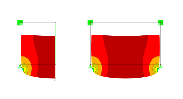
However, there is the option to halve the system and define the corresponding equivalent support; see Image 01.
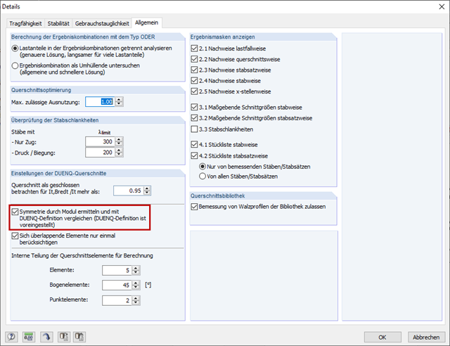
RF‑/ALUMINUM checks the symmetry of general cross-sections and compares them with the SHAPE‑THIN evaluation when activating the "Determine symmetry by module and compare with SHAPE‑THIN definition" check box (Image 01).
If the two methods provide different results, the corresponding error message appears (Image 02).
Usually, there are small inaccuracies in the SHAPE‑THIN cross-section. Thus, the cross-section Sec‑1.du9 shown in Image 03 is not absolutely symmetrical to the Z‑axis: The Z‑coordinates of Node 1 and Node 4 as well as Node 55 and Node 60 do not match in the second decimal place.
SHAPE‑THIN classifies the cross-section as asymmetrical, but RF‑/ALUMINUM as monosymmetric to the z‑axis, so the error message shown in Image 02 appears.
The SHAPE‑THIN cross-section should be checked for symmetry. When modeling in SHAPE‑THIN, it is useful to display only one side of the cross-section and create the other half by mirroring. This is also shown in the video.
1. Selecting another cross-section from cross-section library
2. Reducing section to individual elements
1. Selecting another cross-section from the cross-section library
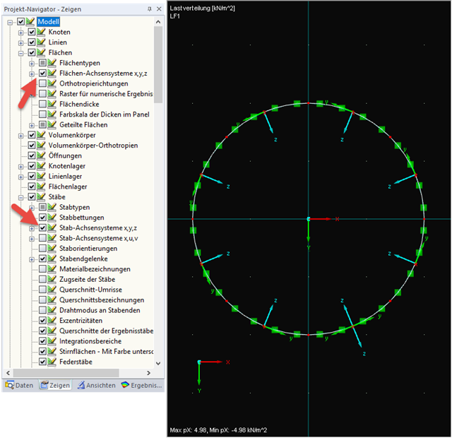
Please check the orientations of all supports, members, and surfaces, and thus, the orientations of the loads. It is useful to display the respective coordinate systems using the Display navigator (Image 01).
If this does not solve the problem, use the simplest possible load case where the deformation is easy to follow. Consult the internal forces and deformations to detect possible rotations or missing connections (Image 02). In order to recognize rotated loads on surfaces, you can also use the "Load Distribution" option in the results (Image 03).
A supposed connection between a surface and a member is often missing. In this case, the FE mesh can also show whether the connection exists.
If the asymmetry remains, use a copy of the model and delete the elements successively to find the cause of the missing symmetry.
If all of this is unsuccessful, please send the model to our hotline with a note of which tests you have already performed.
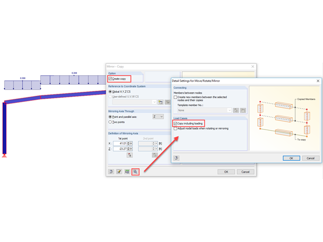
In RFEM and RSTAB, it is not possible to use the symmetry of the structure to calculate only half of the structure.
However, it is possible to create only half of the structure including the loads and then generate the other half using the menu tool "Edit → Select → All" and then "Edit → Mirror". In the Mirror dialog box, it is necessary to select the "Create copy" option and the "Copy including loading" option under [Details] (see Image 01).
This way, you can omit the supports in the mirror axis and obtain more realistic results.